Harris automation system controls the entire place. It contains multiple lists for various functions. The record list has times sources & destinations. It tells the router to switch the selected source (usually a satellite PBS feed) and route it to recording devices usually the seachange video server and a VTR video tape recorder D2 deck. The tape is recorded for a backup in case the video server crashes. The record list also has the time needed to record.
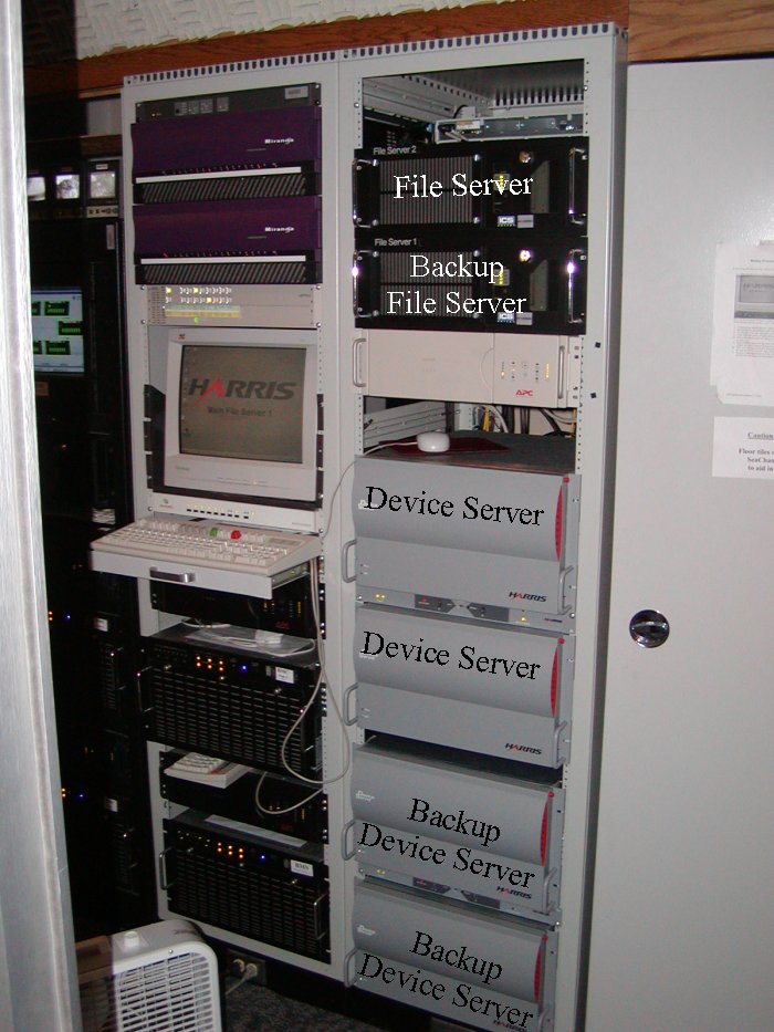
The Harris automation system has two file servers and four device servers. The file servers contain a database that has a list of all the programs that have been recorded, reviewed and check in with the start and stop frames. Both file servers are the same. One is used for backup. The device servers connect to all the devices via RS422. Each server has eight RS 422 cards with eight ports per card. The devices are VTR (video tape recorder), seachange video server, digicart audio clip server, router which controls inputs and outputs, switcher that does fades and other transitions, and other miscellaneous devices. This device server controls anything connected to it. Even standard VCR's are connected to it using contact closures connected to various switches on the VCR, ex: play, record, etc. Two of the four device servers are used for mirrored backup systems. All four servers RS 422 outputs are connected to a 4066 switch panel controlled by the Harris automation computer. This switches between main and backup.
The Air Client software is running on a Windows NT computer. The air client has the play list for video clips to be aired. The list has the source (usually the seachange video server, and some times VTR tape decks are used. ) The destination is the transmitter. The time factor in the list is very important. It contains start and stop times of every video segment to be aired. 30 frames / sec. The automation system accounts for every 1/30 of a second.
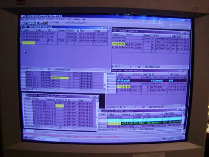
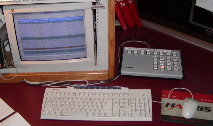
The picture below shows the record list for the Harris Air Client. The left side is for VTR records and the right side is for server records. The record list shows the time, title, ID, device source, destination, status, type and duration.
The broadcast play list is also on Harris Air Client shown below. It also shows time, title, ID, device source, destination, status, type and duration. Protrack software is used by traffic department to create a play list schedule. The list contains the programs to be aired. The coding schemes are as follows. AO command is a hard start. It is used when a program is set to start at a specific time. For instance, Nova comes down from the satellite exactly at 7:00 PM Tuesday. The AO command will air Nova at 7:00 PM regardless of any other video segment that is currently airing. In other words, the current show will be cut off when Nova starts. AU waits for the previous show to end before the next program airs. This list is imported into the Harris Air Client.
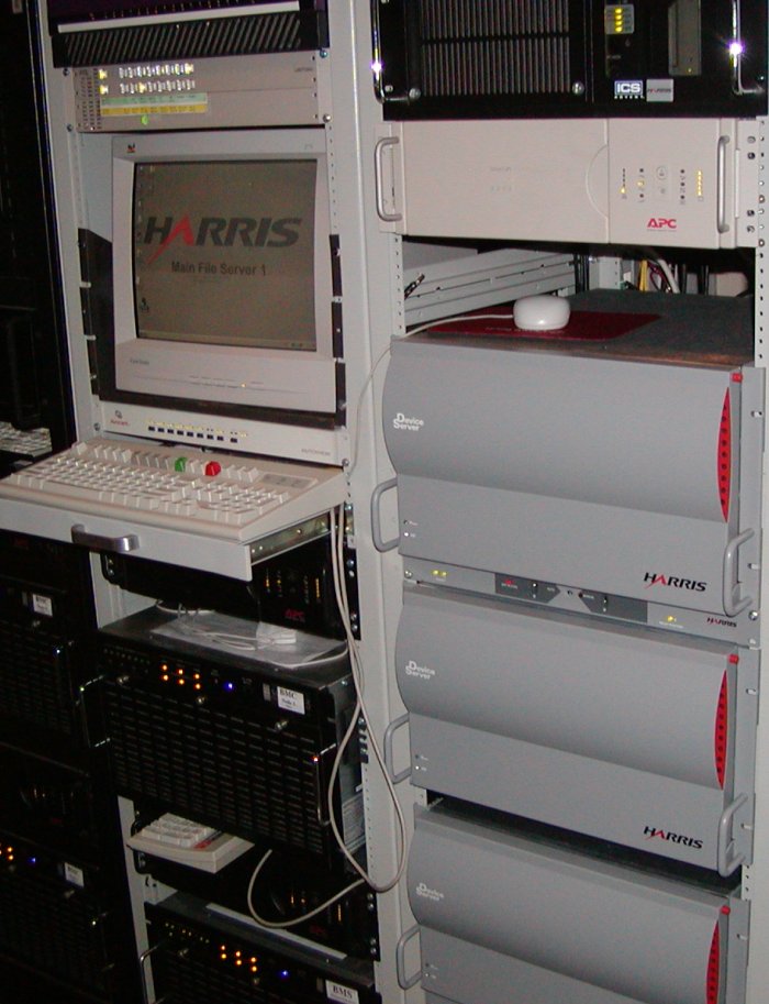
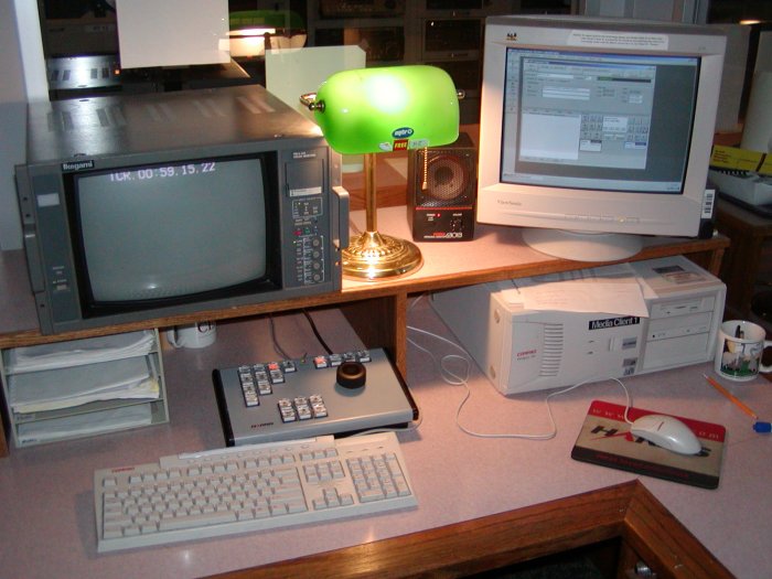
The picture below shows the ingest station. The monitor on the left displays the video clip with the time code. The computer on the right is running Media Client software and it is used to enter the start and stop of the video clips that reside on the Seachange or VTRs into the Harris database. The database contains all the information about the videos and contains all the play and record lists for all Channels 10, 35-HD, and 36.
As mentioned earlier, Harris contorts devices via RS 422. This standard is based on RS 232
RS - recommend standard. This is used for serial digital communication.
RS 232 is (+ or -) 12-volt signal representing 0 or 1 respectively using unbalanced communication line (wire.) The standard will allow +5 to +25 volts to represent a 0 (space) and -5 to -25 volts represents a 1 (mark). RS 232 was used often and has been revised a few times. The problem is distance between devices, less than 50 feet at 20Kbps. When the signal changes from one state to the other, the specification limits the amount of transition time to 5 percent of the bit period. This limits the amount of stray capacitance allowed in the wires. The maximum capacitance allowed is 2500 pF. Wires used for RS 232 generally have 50 pF per foot, limiting total distance to 50 feet. Capacitance opposes a voltage change. With stray capacitance in the wire, the voltage may not change fast enough and then errors in data occur. The maximum speed the serial port can handle is 115 Kbps. The cable must be very short, 6 feet.
RS 422 is an improved version of the RS232 and this is widely used in Television Station controls. It is (0 or + 5) volt signal representing 0 or 1 respectively using balanced communication line. The minimum voltage difference for RS 232 is 6 volts, +3 to -3, when RS 422A is only 0.4 volts. Using a balance line with no ground reference allows faster transitions from one state to the other therefore achieving faster data transfer.
Balanced verses Unbalanced line. With a balanced line the signal is derived by the difference between the voltages. The system uses two wire pairs for each data direction without common ground. This allows high-speed communication without errors.
Unbalanced line is when data wires use a common chassis ground wire of each device. Ground potentials over distances can differ causing data errors.
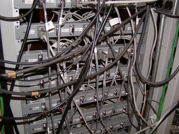
The photo below shows the RS422 Device Server Output
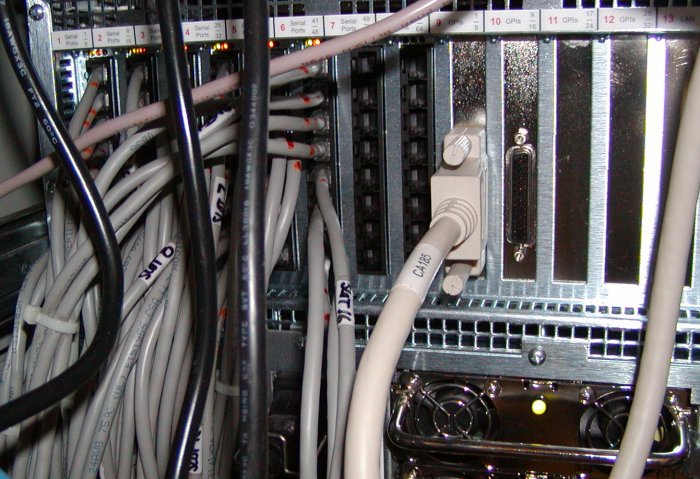
Below shows the device server RS422 outputs that are connected to a 4066 switch panel. Both the main and backup device server outputs are connected here. The computer switches the backup server and its RS422 outputs into operation when needed.