Timing Diagrams
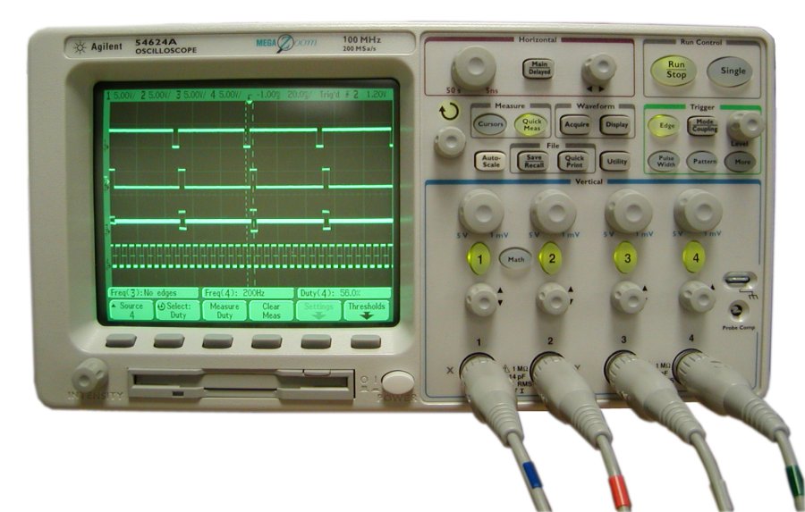
Timing is very important. The clock runs at 200 Hz, 5 ms. The clock feeds the counter, when it reaches 1010, it triggers the RD timer. The read timer is active high for 45 ms and off for 5 ms, but using the not-Q pin. The signals are inverted. The 5 ms pulse is now high which activates the PAM circuit. The read timer on the low to high transition triggers the WR timer. The WR timer is high for 45 ms and off for 5 ms. 40 of the 45 ms of the low pulse of the RD timer is used for reading the data of the data buss of the ADC. The ADC has a tri-state latch for its 8 - bit output buss. The data is held there until each output is read by the multiplexer, 5 ms per read, times 8 reads = 40 ms. The data is pulsed out at the clock rate of 5 ms. It starts with the lsb up to the msb. The msb is the sign bit to show positive or negative value. One additional bit is masked by the embedded clock bit. The frame, or one complete cycle is 10 clock pulses or 50 ms. The scope capture shows the precise timing of the system
The Analog signal, in this case, a sine wave, is sampled and converted to a PCM stream. Pulse code modulation with NRZ, non-return to zero line code is transmitted and then received decoded. The transmission can be through wires or the air. The binary bit stream can be modulated with an RF carrier and sent through the air. The data also can be sent via fiber optics. If the data is sent through a narrow bandwidth system, the NRZ line code will be converted to an move efficient line code depending on the application. Once the signal is received on the other end, the reverse must be done. For wireless systems, the RF carrier must be removed and the baseband code recovered. The data then is decoded and put back into binary NRZ. The timing is very important. Often clock pulses are sent before any data is sent to synchronize the receive clock. Symbols sent before and / or after the data is known as preamble. Using a digital to analog converter the original signal can be recreated with reasonable accuracy. With higher sampling rates the recovered signal will be better. The downfall is larger amounts of data has to be processed and sent through a channel and recovered.
Below is the Schematic for the ADC PCM