|
|
Telephone on hold with Music |
|
|
|
Telephone on hold with Music |
|
The Telephone on hold circuit will put the caller on hold with music after pressing the pound (#) key.
The circuit meets all the FCC Part 68 regulations of isolating and loading the telephone line.
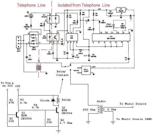
Schematic of universal hold circuit modified for delivering Music-On-Hold
When a button on the phone is pushed, it creates dual tones for signaling. This is known as DTMF. "Dual Tone Multi Frequency"
The CD22204 DTMF decoder chip decodes the touch-tone into binary digits. The table below shows the outputs D1 – D8 of the decoder chip.
|
Digit |
D8 |
D4 |
D2 |
D1 |
|
1 |
0 |
0 |
0 |
1 |
|
2 |
0 |
0 |
1 |
0 |
|
3 |
0 |
0 |
1 |
1 |
|
4 |
0 |
1 |
0 |
0 |
|
5 |
0 |
1 |
0 |
1 |
|
6 |
0 |
1 |
1 |
0 |
|
7 |
0 |
1 |
1 |
1 |
|
8 |
1 |
0 |
0 |
0 |
|
9 |
1 |
0 |
0 |
1 |
|
0 |
1 |
0 |
1 |
0 |
|
* |
1 |
0 |
1 |
1 |
|
# |
1 |
1 |
0 |
0 |
|
A |
1 |
1 |
0 |
1 |
|
B |
1 |
1 |
1 |
0 |
|
C |
1 |
1 |
1 |
1 |
|
D |
0 |
0 |
0 |
0 |
Circuit Operation
The pound key is used to activate the hold circuit. Output D8 & D4 on pins 14 &13 on the CD22204 are active high (+5 volts) when the pound key is pressed. Capacitor C1 is charged when the circuit is powered up. When the pound key is pressed, pins 14 &13 go high and discharge C1 creating a charge pumping action reversing polarity on C1 forcing pin 2 low on the 555 timer thus triggering the timing cycle. The timing cycle is based on the capacitor C7 discharging through resistor R7. Pin 3 on the 555 timer goes high during the timing cycle. This output activates optocoupler H11C1 and therefore creating a current loop on the telephone circuit that will draw enough current to hold the line open after the phone is hung up. If the phone is not hung up, the 555 timer will complete its timing cycle pin 3 goes low and the optocoupler shuts off and disables the current loop. If the phone is hung up before the 555 completes the timing cycle, the hold circuit is activated. Once it is activated, optocoupler 4N28 sends a feedback signal to the 555 timer on pin 4 to reset the timer and also energizes a relay to inject music into the telephone line while remaining on hold. If any phone is picked up, it draws more current than the hold circuit current loop and the SCR inside the optocoupler turns off and resets the circuit. The SCR is used because of its latching properties.
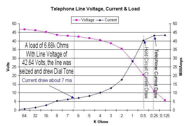
The chart below shows the current draw of the telephone and hold circuit. A current draw as little as 7 ma (milliamps) is enough to signal the phone switch to seize the line (make a connection) and insert dial tone. A telephone draws about 43 ma. The hold circuit draws around 40 ma.
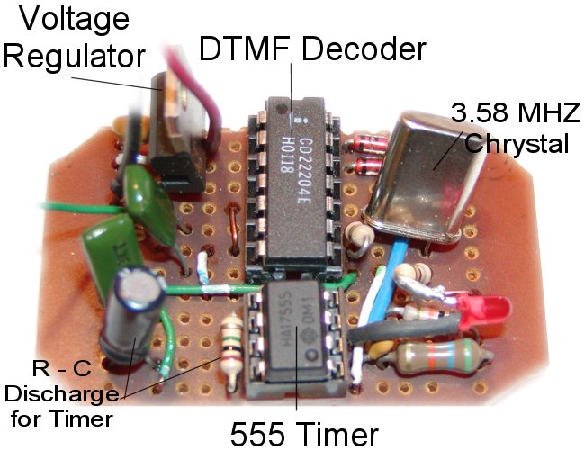
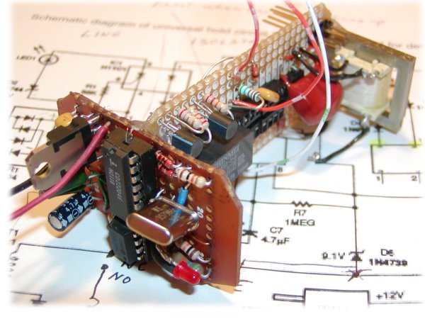
The picture below is the first part of the circuit. This circuit has a voltage regular 78L05 to hold the circuit voltage to 5 volts DC. A 1N4739 zener diode is in the circuit for added voltage regulation. CD22204 DTMF decoder chip output pins 13 & 14 have diodes connected for the charge pumping circuit. The chip needs a 3.579545 MHZ crystal for operation. The 555 timer chip uses a R – C network for timing. R – C (resistor – capacitor) is a 4.7-microfarad capacitor that is discharged slowly through the 1 million ohm resistor. RC time constant is calculated by R * C = Time. 1,000,000 * 0.0000047 = 4.7 seconds.
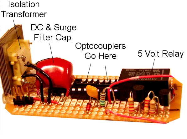
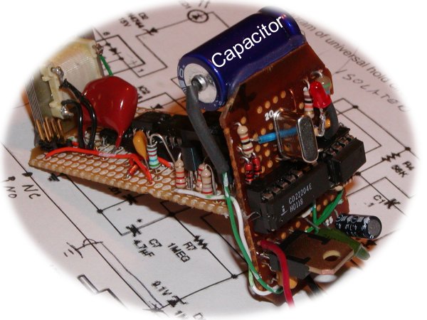
The second part of the circuit has the optocouplers, isolation transformer, music activation relay and current direction bridge rectifier. Below, the big transformer is to isolate this circuit from the telephone network. The FCC has regulations to protect the phone network from damage and external noise. FCC Part 68 rules are for telecommunications. The capacitor blocks the DC from this circuit from traveling back into the phone system. The optocouplers or optoisolaters are also needed to isolate control signals. The relay switches the telephone lines from the DTMF decoder chip to the music source. This relay also turns the radio on.
The circuit boards are put together and completed below.
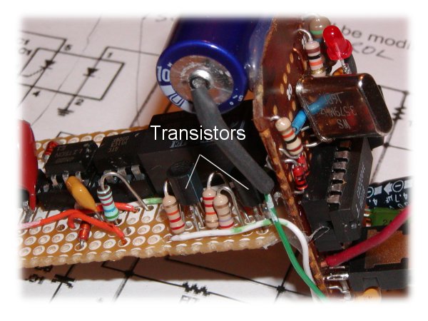
The transistors in this circuit are needed to drive the relay. The output of the optocoupler doesn’t have power to drive the relay. The transistors act like switches. The first one inverts the signal. Because when the base is off, no voltage, the collector is on, 5 volts. The first transistor’s output, the collector, feeds into the base of the second transistor. The second transistor does the switching on the coil of the relay.
The big blue 1000-microfarad capacitor in the picture below filters out any voltage fluctuations.
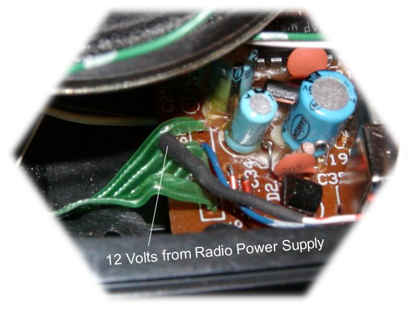
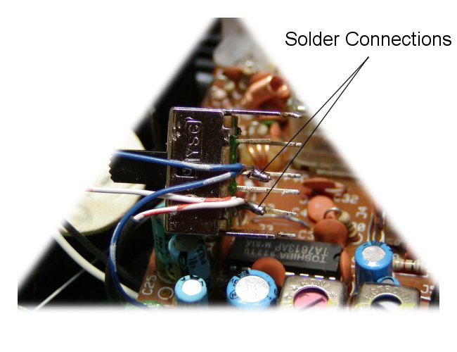
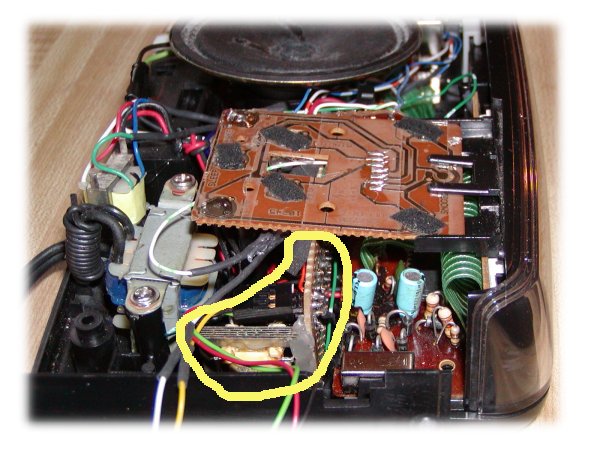
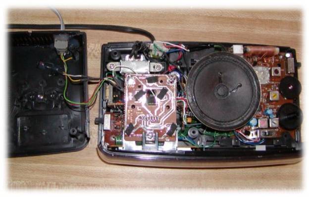
This hold circuit is going to be installed into a clock radio. The radio runs on 12 volts DC. The hold circuit needs power from the radio. Its voltage regulator will cut down the voltage to 5 VDC. The following picture shows where the 12 volts was taken from.
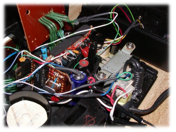
The relay in the hold circuit turns the radio on. Wires had to be soldered across the On – Off switch of the radio that connected to the relay for automatic operation. The switch had to de-soldered from the radio circuit board below.
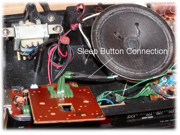
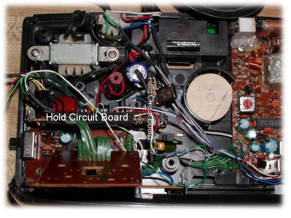
The radio had a sleep button that was not being used anymore. The hold circuit was connected to that button. Now either the sleep button or the pound key on the phone can activate the hold circuit. The connection is shown below. Note the open space. This is where the hold circuit will snugly fit.
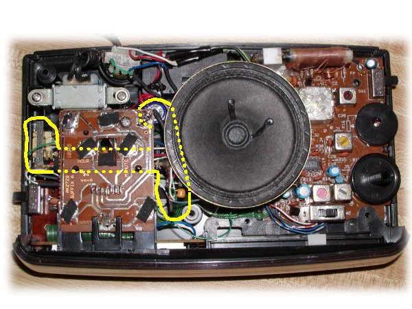
Inserting the Hold Circuit board
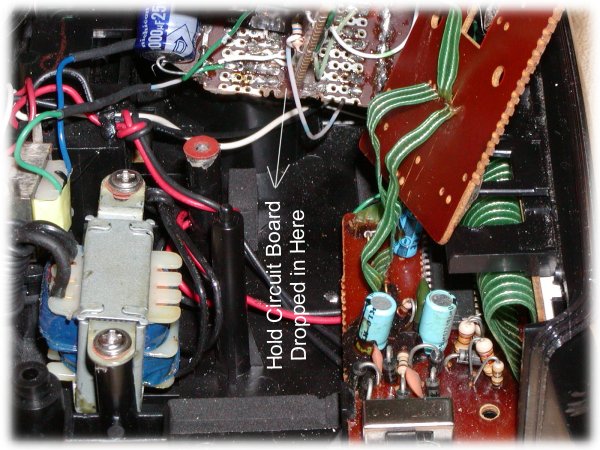
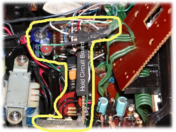
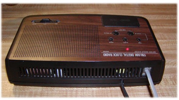
The hold circuit board fits in the clock radio like it was designed that way from the factory.
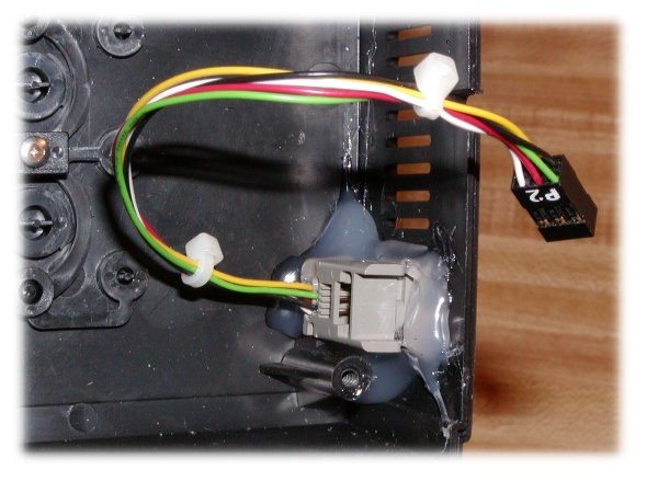
The RJ11 phone socket was hot glued into clock case.
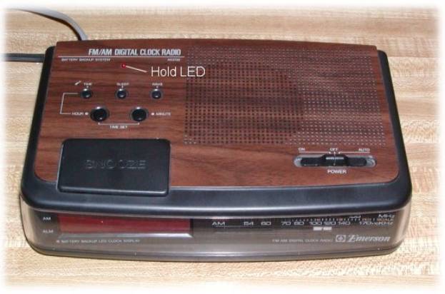
The hold LED shows when a caller is on hold.
This clock radio was modified with music on hold circuit by Mike Luisa November 2004.